
Logic Gateway
1. Introduction to Logic Gates & Truth Tables
Welcome to Logic Gateway. To understand computers, machinery, and software, you must first understand the fundamental building blocks of digital logic: Logic Gates.
At their core, digital circuits operate on binary values. Everything is reduced to two states: 1 (True / On / High Voltage) or 0 (False / Off / Low Voltage). A logic gate is simply a physical device or software construct that takes one or more of these binary inputs, evaluates them according to a specific rule, and produces a single binary output.
The Primary Gates
Below is your visual guide to the standard logic gates we will be utilizing in your circuits. Study their shapes and operational rules carefully.
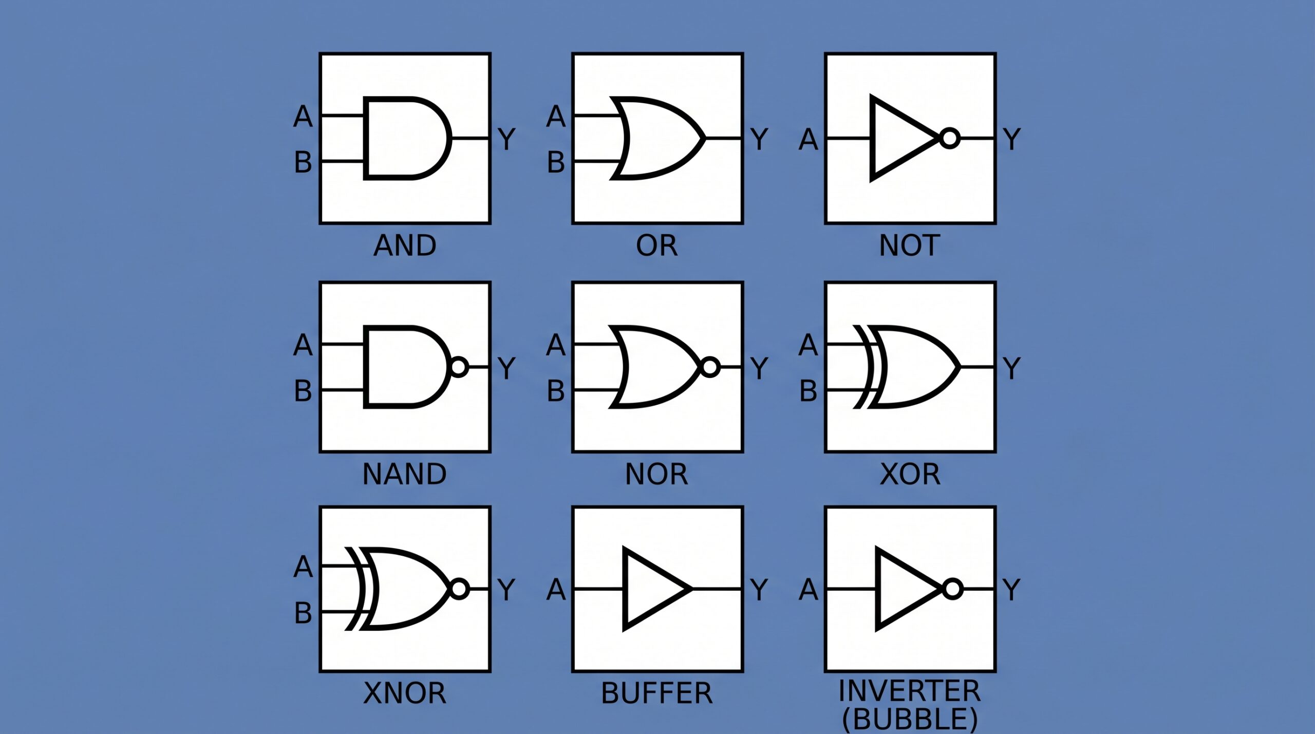
- AND Gate: Requires all conditions to be met. The output is 1 only if input A and input B are both 1. Otherwise, the output is 0.
- OR Gate: Highly permissive. The output is 1 if input A or input B (or both) are 1. The output is 0 only if all inputs are 0.
- NOT Gate (Inverter): The rebel. It only has one input, and it simply flips it. If you input a 1, it outputs a 0. If you input a 0, it outputs a 1.
- NAND Gate (NOT-AND): The exact opposite of an AND gate. The output is 0 only if all inputs are 1. In all other scenarios, it outputs a 1.
- NOR Gate (NOT-OR): The exact opposite of an OR gate. The output is 1 only if all inputs are exactly 0. Any input of 1 forces the output to 0.
- XOR Gate (Exclusive OR): The strict discriminator. The output is 1 only if the inputs are different from each other (e.g., A is 1, B is 0). If the inputs are the same, it outputs 0.
- XNOR Gate (Exclusive NOR): The conformity gate. The output is 1 only if the inputs match perfectly (both 1, or both 0). If they differ, it outputs 0.
- Buffer: The messenger. It outputs exactly what is input into it. While logically it changes nothing, in physical hardware it is used to boost signal strength or create calculated timing delays.
The Inversion Bubble
Notice the small circle on the output side of the NOT, NAND, and NOR gates? That is called an inversion bubble. In digital logic design, a bubble attached to any input or output pin automatically applies a NOT operation at that specific point, flipping the signal from 1 to 0 (or 0 to 1) before it continues on its path.
Truth Tables: The Mathematical Cheat Sheet
Once you understand how a gate works, you can map out its behavior using a Truth Table. A truth table lists every possible combination of inputs a gate could receive, and explicitly states what the output will be for that specific combination. In our notation, inputs are labeled A and B, and the final output is labeled Y.
Let's look at how the rules of the gates translate into truth tables:
| A | B | Y |
|---|---|---|
| 0 | 0 | 0 |
| 0 | 1 | 0 |
| 1 | 0 | 0 |
| 1 | 1 | 1 |
| A | B | Y |
|---|---|---|
| 0 | 0 | 0 |
| 0 | 1 | 1 |
| 1 | 0 | 1 |
| 1 | 1 | 1 |
| A | B | Y |
|---|---|---|
| 0 | 0 | 0 |
| 0 | 1 | 1 |
| 1 | 0 | 1 |
| 1 | 1 | 0 |
| A | - | Y |
|---|---|---|
| 0 | - | 1 |
| 1 | - | 0 |
By learning to read these tables, you can quickly evaluate complex circuits by tracing the 1s and 0s from the beginning of the line all the way to the final output.